General Questions
- How long is each session?
- Can I save my preferences or changes on GeneTV?
- How many KOMP and EUCOMM projects have been retrieved and analyzed by GeneTV?
- When was the projects retrieved from KOMP and EUCOMM repositories?
- What if the gene or project of my interest has not been retrieved or analyzed by GeneTV but is available by KOMP or EUCOMM?
- What is the Try Now button?
Navigation
- What are the search terms that I can use to search?
- What does the Show All button do?
- What is the Project List?
- What are the headings on the Project List page mean?
- What is the Targeting Vectors page?
- How do I get to Ensembl to confirm the Transcript ID?
- What is Vector ID on the Targeting Vectors page?
- What is the Design ID on the Targeting Vectors page?
- What is the TV Sequence on the Targeting Vectors page?
- What are the headings on the Targeting Vectors page for Velocigene projects?
Targeting Vector Design Interactive Tool
- How do I get to the Targeting Vector Design program?
- What modifications can I made on the Targeting Vector Design program?
- Can I save my changes on the Targeting Vector Design program?
- How come the Exon ID for my gene of interest is different on the schematic diagram than Ensembl?
Key Functions on Left Column
Project Information
- What is Project Keys?
- How do I modify the WT sequence of my project to make the flanking sequence longer or shorter?
Construct
- How do I select an enzyme to display all possible cutting sites on the schematic diagram?
- How do I remove the selected enzyme(s) from displaying on the schematic diagram?
- How do I design a probe for Southern blot?
- What are probe candidates listed in the Define Probe page?
- How do I design a Neo probe for Southern blot?
- What is the self-designed probe on the Define Probes page?
- How do I modify my probe after I have designed it?
- How do I delete my probe after I have entered it?
- How do I change the way my probe displayed on the schematic diagram?
- How do I display a Southern strategy of a specified probe and enzyme on the schematic diagram?
- How do I display a Southern strategy with two probes and enzymes on the schematic diagram?
- How do I remove the selected Southern enzyme from displaying on the schematic diagram?
- If I’d like to replace any of the TV components with another sequence (i.e. to replace Neo with Hygromycin or LacZ with GFP), how would I go about doing it?
- How do I modify the title on the schematic diagram?
- How do I modify the description on the schematic diagram?
Construct Strategies
- How do I display the schematic diagram after FLP recombinase has been introduced?
- How do I display the schematic diagram after Cre recombinase has been introduced?
Reporting
- How do I view possible Southern strategies including enzymes and expected sizes for a specific probe?
- How come I didn’t get a Southern report after I entered my probe?
- What is the difference between Project Report and Client Report?
- What is the difference between WT and TV on Project Report and Client Report?
Screening and QC
- What is Design Oligos?
- How do I display oligos on the schematic diagram and client report?
- How do I display some but not all oligos on the schematic diagram or the client report?
- How do I find the expected size for PCR amplification for an oligo or primer pair?
- How do I design my own PCR oligo or primer and display it on the schematic diagram or the client report?
- What is a TV QC page?
Key Functions on Top Panel
- How do I get to the Ensembl website from the Targeting Vector Design page?
- How do I display my selected targeting vector on the schematic diagram?
- What is displayed on the schematic diagram?
- How do I hide the schematic diagram?
- How do I display my selected oligos on the schematic diagram?
Schematic Options
- How do I change the font style and size for the title on the schematic diagram?
- How do I change the font style and size for the description on the schematic diagram?
- How do I display/hide my designed probe(s) on the schematic diagram?
- How do I display the relative distance or size on the schematic diagram?
- What is the static or interactive button on the schematic diagram?
- How do I show/hide all the labels on the schematic diagram?
- Can I save the schematic diagram?
- Can I download the schematic diagram?
- How do I zoom in to see details of the schematic diagram?
General Questions
- How long is each session?
Each session is 20 minutes of continuous keystroke activity. If your computer is idle, a prompt will be flashed up on your screen when the last 5 minutes is to be expired. By hitting any keys, it will renew you for another 20 minutes. When your session ends, the Project List will be displayed. In this version you will not be able to save data, please see below.
- Can I save my preferences or changes on GeneTV?
No, you cannot save any preferences or changes on GeneTV. A later version will be released to allow registered users to save preferences and changes for their projects.
- How many KOMP and EUCOMM projects have been retrieved and analyzed by GeneTV?
A total of 17,171 projects have been retrieved and analyzed by GeneTV. 14,002 projects are from KOMP and 3,169 projects are from EUCOMM. A list of projects that were not retrieved or analyzed by GeneTV is provided on the Project List page.
- When were the projects retrieved from KOMP and EUCOMM repositories?
Projects were retrieved from KOMP and EUCOMM repositories from February 2011 through June 2011. If there were any changes from KOMP or EUCOMM since then, the changes will not have been updated on GeneTV.
- What if the gene or project of my interest has not been retrieved or analyzed by GeneTV but
is available by KOMP or EUCOMM?
Please email us your gene of interest and the project ID # to info@mousegps.com.
- What is the Try Now button?
The Try Now button is to provide you an opportunity to input and upload your project of interest using our Targeting Vector Design Interactive Tool program. Note that any information uploaded will not be saved.
Navigation
-
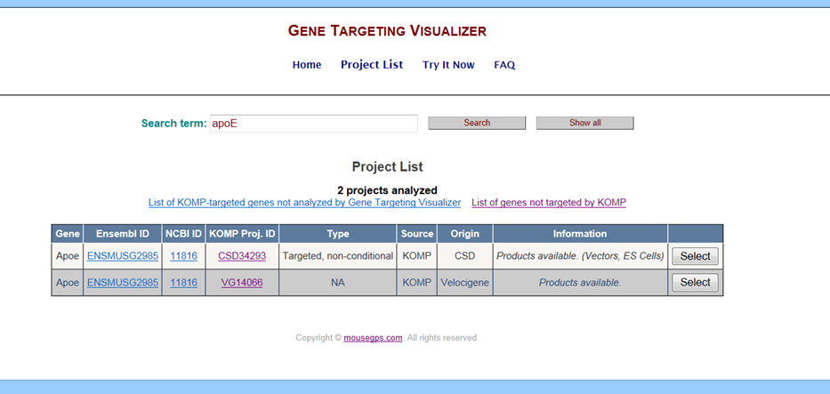
Enter any of the below information in the Search term box and press Search button:
- name
- Ensembl ID
- NCBI ID
- KOMP Project ID
Below is an example of search results for ApoE gene.
-
The Show All button will take you to the main page with a list of all projects.
-
The Project List includes KOMP and EUCOMM projects that have been retrieved and analyzed by GeneTV.
-

- Gene – Provides the gene name for your project of interest.
- Ensembl ID – Provides a link to Ensembl website (http://www.ensembl.org/index.html for your selected gene.
- NCBI ID – Provides a link to NCBI website (http://www.ncbi.nlm.nih.gov/gene for your selected gene.
- KOMP Proj ID – Provides a link to IKMC or Velocigene to view the details for your project of interest.
- Type – Provides the allele type of targeting strategy for your project of interest. Details about various allele types can be found at this link: https://www.komp.org/alleles.php#conditional-promoter-csd. If the Type is listed “NA” or left blank, information was not provided from the IKMC database.
- Source – Provides which repository the product was made: KOMP or EUCOMM.
- Origin – Provides which group the vector or product was made from: CSD, Velicogene, or Sanger.
- Information – Provides a list of available products for your project of interest: vectors or vectors and ES cells.
-
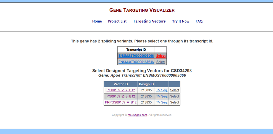
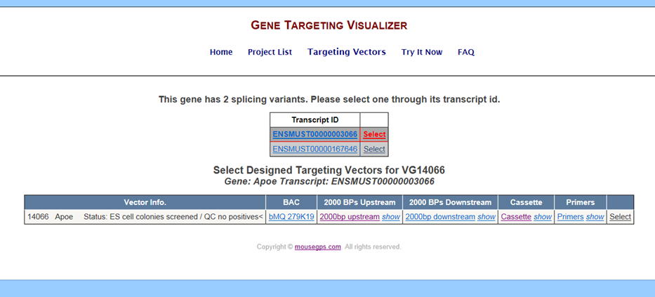
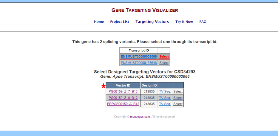
The Targeting Vectors page lists all targeting vectors available for your selected project of interest.
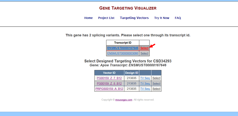
Below is an example of the Targeting Vectors page for CSD/EUCOMM projects:
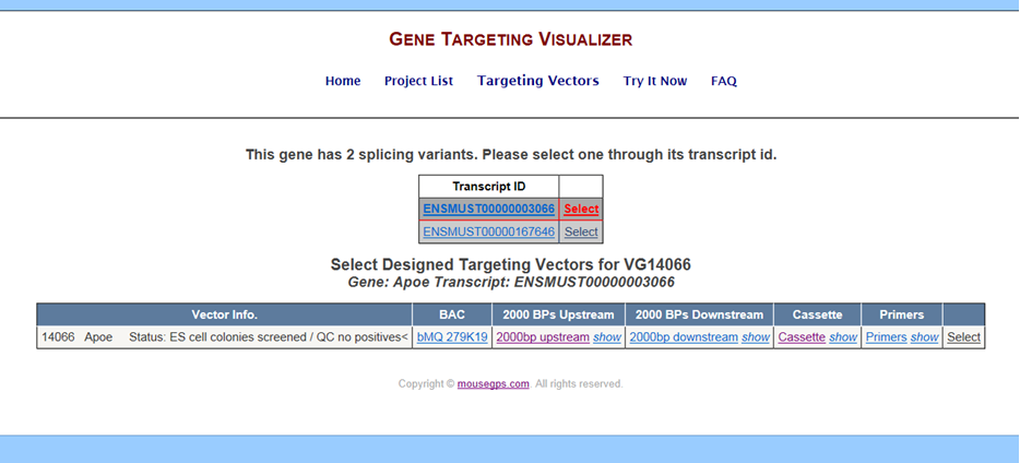
Below is an exmample of the Targeting Vectors page for Velocigene projects:
-
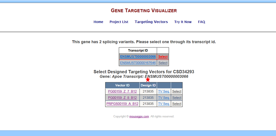
Go to the Targeting Vectors page and click on the link under Transcript ID. It will take you to the Ensembl website for your gene of interest and the selected transcript.
-
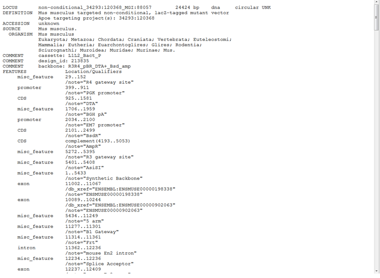
The Vector ID is the Targeting Vector ID generated from KOMP or EUCOMM. When clicking on a specific Vector ID, a page will be opened from IKMC showing the GenBank file for the selected targeting vector.
Below is an example of the GenBank file for ApoE gene (Vector ID PB00159_Z7_B12):
-
The Design ID is the targeting strategy used for generating the targeting vectors.
-
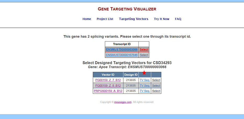
The TV Sequence is the GenBank file for the selected targeting vector that was uploaded from February 2011 through June 2011 onto GeneTV. This GenBank file was used to generate the schematic diagram. The latest GenBank file for the selected targeting vector can be found by clicking on the Vector ID. Any changes from KOMP/EUCOMM will not be displayed on the GenBank file for the TV Sequence.
-
- Vector ID – provides vector ID, gene name, and status of the project.
- BAC – displays wild-type sequence used for generating the BAC targeting vector.
- 2000 BPs Upstream – displays 2000bps upstream of the deletion region.
- 2000 BPs Downstream – displays 2000bps downstream of the deletion region.
- Cassette – displays the selection and reporter cassettes which replace the deletion region.
- Primers – displays primers designed by Velocigene for the selected targeting vector.
Targeting Vector Design Interactive Tool
- How do I get to the Targeting Vector Design program?
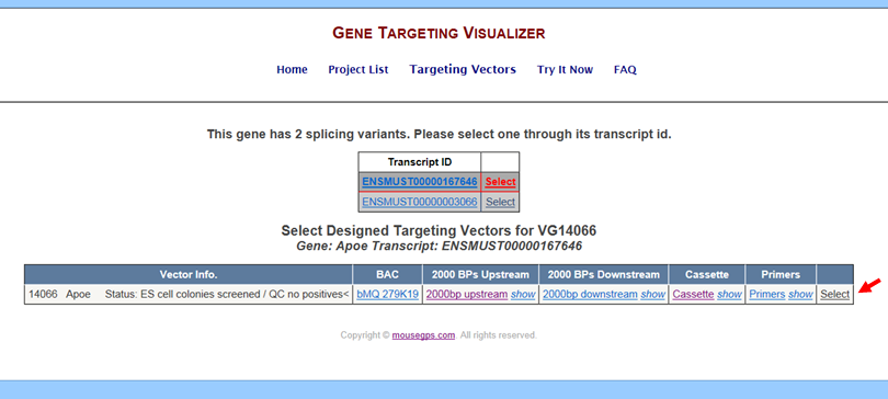
Go to the Targeting Vectors page for your selected project of interest. Click the Select button next to the Vector Name of your choice. It will take you to the Targeting Vector Design Interactive Tool program.
For CSD and EUCOMM targeting vectors:
For Velocigene targeting vectors:
- What modifications can I made on the Targeting Vector Design program?
Below are some modifications that you could make on the Targeting Vector Design program:
- Design your own probes and Southern strategy
- Design your own oligos and display on schematic diagram
- Change schematic title and description
- Change flanking region outside 5’ and 3’ arms
- Replace a different sequence for selection cassette or any vector components
- Etc.
Note that any modifications can be updated for your project of interest during your session but cannot be saved. After your session has been expired or when you selected another project, any modifications you made cannot be retrieved.
- Can I save my changes on the Targeting Vector Design program?
No, you cannot save your changes on the Targeting Vector Design program. A later version will be published shortly to allow you to save your changes using your login account.
- How come the Exon ID for my gene of interest is different on the schematic diagram than Ensembl?
The sequence of the gene and its Exon IDs were retrieved from Ensembl from February 2011 through June 2011. If Ensembl has updated your gene of interest since then, the changes will not updated on GeneTV. Although the Exon ID might have changed, check and blast the exon sequences to Ensembl to see if the sequences have changed as well.
Key Functions on Left Column
Project Information
- What is Project Keys?
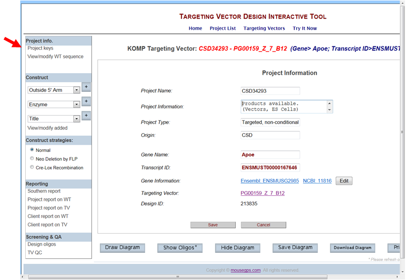
In the Project Info section on the left-hand column, click Project Keys. The Project Keys provide pertinent information relating to your selected project of interest. Project Information page contains the project ID#, products availability from KOMP, project type, origin of the targeting vector, gene name, links to Ensembl and NCBI for the gene, targeting vector name, and the design ID#.
- How do I modify the WT sequence of my project to make the flanking sequence longer or shorter?
In the Project Info section on the left-hand column, click View/modify WT Sequence. Paste your new sequence or delete existing sequence in the flanking region of the 5’ or 3’ end. Click Load/upload button to save your changes.
* Note when your session ends or if you select another project, your changes cannot be retrieved.
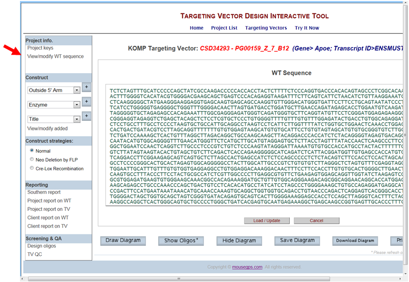
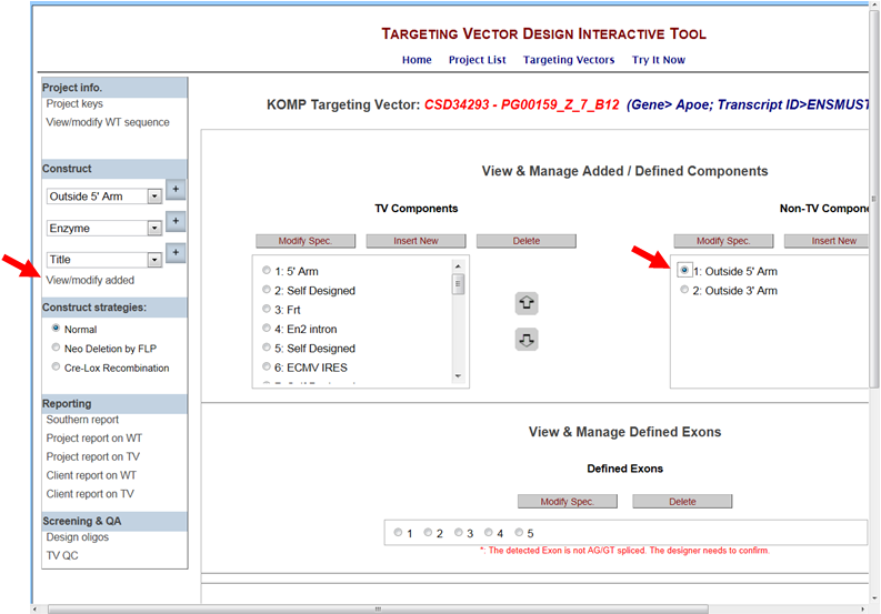
Then click on View/modify added in the Construct section on the left-hand column. It will take you the View & Manage Added/Defined Components page. In the Non-TV Components box on the right, click on the bubble for Outside 5’ or 3’ arm that you’d like to modify. Click Modify Spec button.
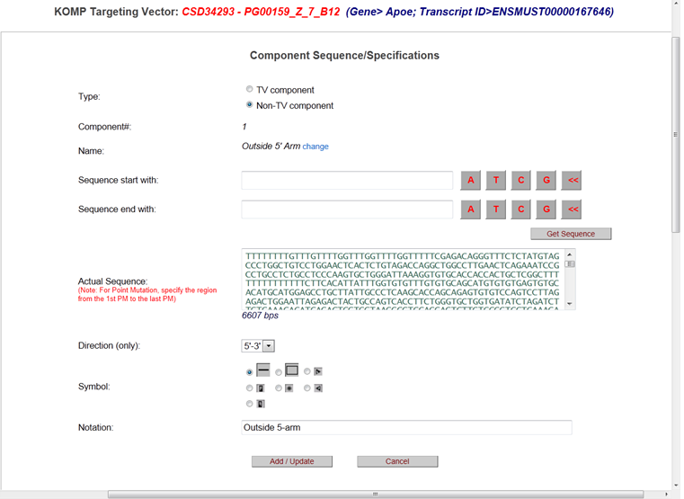
It will take you to the Component Sequence Specifications page. Again, add your new sequence or delete the existing sequence to the Actual Sequence box. Then click Add/Upload button. Click Draw or Draw Diagram to visualize changes on the schematic diagram or click Project or Client report to retrieve the entire sequence with new flanking region(s).
Construct
- How do I select an enzyme to display all possible cutting sites on the schematic diagram?
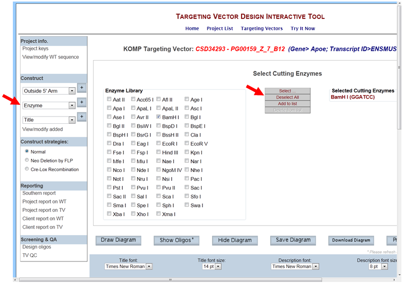
In the Construct section on the left-hand column, select Enzyme and click the [+] button. It will take you to the Select Cutting Enzymes page. The Enzyme library has 55 unique enzymes to choose from. Select the enzyme of your choice by checking off the box next to your enzyme. Then click Select button. Your selected enzyme will be listed on the right side of the screen. You can select multiple enzymes by checking off the boxes and then click Select. If you want to clear all of your selected enzymes, click Deselect All button or remove the check from the box next to the enzyme.
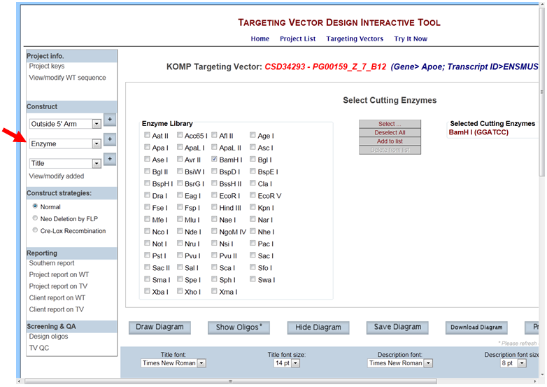
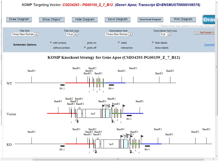
Click Draw or Draw Diagram and all possible cutting sites for your selected enzyme will be displayed on the schematic diagram. Below is an example of all possible cutting sites for the selected enzyme Bam HI.
- How do I remove the selected enzyme(s) from displaying on the schematic diagram?
In the Construct section on the left-hand column, select Enzyme from the drop-down menu and click the [+] button. It will take you to the Select Cutting Enzymes page. Click Deselect All button to clear all selected enzymes or remove the check from the box next to the enzyme to deselect a specific enzyme.
- How do I design a probe for Southern blot?
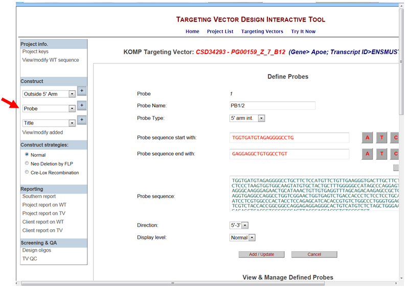
In the Construct section on the left-hand column, select Probe from the drop-down menu and click the [+] button. It will take you to the Define Probes page. Enter your Probe Name and use the drop-down menu to select your Probe Type (5’ external/internal; 3’ external/internal; Neo; self-designed). The probe type indicates the location of your probe. If your probe is located outside of the 5’ or 3’ arm, it is considered as 5’ or 3’ arm external. If your probe is located inside the 5’ or 3’ arm, it is considered as 5’ or 3’ arm internal. Note your internal probe cannot be part of a vector component (i.e. cassette). Note your internal probe cannot be part of a vector component (i.e. cassette). If you design a probe inside any other part of a cassette, select self-designed for probe type. If you design a probe inside the Neo cassette, select Neo for probe type. Note that a Southern report will be generated for self-designed probes.
Enter the start and end sequences (5’->3’) of your probe (a minimum of 10 bases) per entry. To enter the sequences, you have the option to type or select the base boxes on the left panel. The box << is for backspace or deletion. Then press Get Sequence button. The entire sequence of your probe will be displayed in the Probe Sequence box. If any base was incorrectly entered, sequences will not be displayed in the Probe Sequence box and an error message will be prompted.
You also have the option to paste the entire probe sequence directly into the Probe Sequence box.
Click Add/Update to add your designed probe.
* Note when your session ends or if you select another project, your designed probe(s) cannot be retrieved.
- What are probe candidates listed in the Define Probe page?
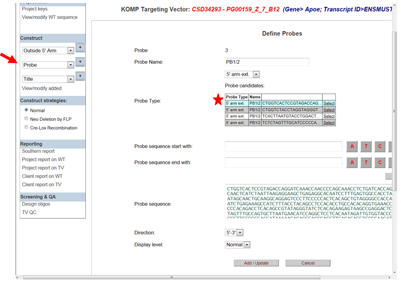
If you don’t know which external probe to design, the list of probe candidates will suggest some potential probes with minimal repeats for upstream or downstream of the 5’ or 3’ homology arms of the targeting vector, respectively. First, you will need to enter the Probe Name and use the drop-down menu to select your Probe Type (5’ external or 3’ external). Then the list of probe candidates will be displayed according to the selection of Probe Type. The probe on top of the list will be located closest to the targeting vector. Click Select next to the probe listed and the entire probe sequence will be displayed in the Probe Sequence box.
Click Add/Update to add your selected probe.
* Note when your session ends or if you select another project, your designed probe(s) cannot be retrieved.
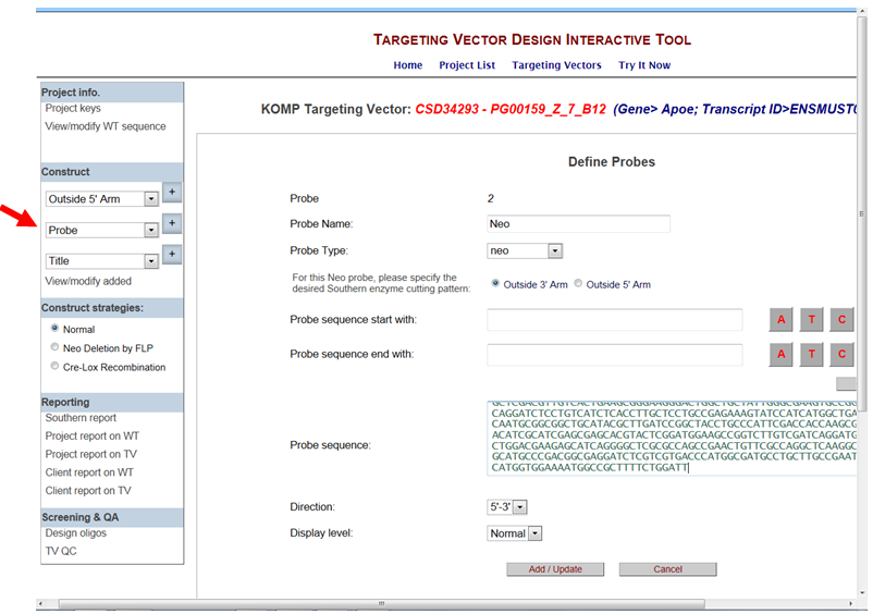
- How do I design a Neo probe for Southern blot?
In the Construct section on the left-hand column, select Probe from the drop-down menu and click the [+] button. It will take you to the Define Probes page. Enter your Probe Name and use the drop-down menu to select Neo for the Probe Type. A prompt will ask you to select the strategy for outside 5’ or 3’ arm. A Southern report will be provided based on which arm you selected. Enter the start and end sequences for your Neo probe and then press Get Sequence button or paste the entire Neo probe sequence into the Probe Sequence box.
Click Add/Update to add your Neo probe.
* Note when your session ends or if you select another project, your designed Neo probe cannot be retrieved.
- What is the self-designed probe on the Define Probes page?
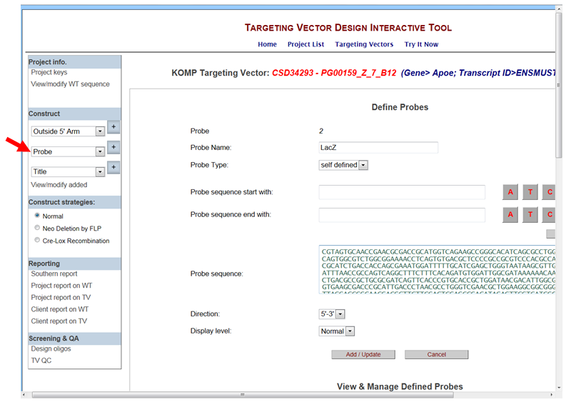
A self-designed probe is located inside or in a part of the vector component (i.e. cassette). A Southern report will not be generated for self-designed probes.
In the Construct section on the left-hand column, select Probe from the drop-down menu and click the [+] button. It will take you to the Define Probes page. Enter your Probe Name and use the drop-down menu to select Self-Designed for the Probe Type. Enter the start and end sequences for your self-designed probe and then press Get Sequence button or paste the entire probe sequence into the Probe Sequence box. Click Add/Update to add your self-designed probe.
* Note when your session ends or if you select another project, your designed Neo probe cannot be retrieved.
- How do I modify my probe after I have designed it?
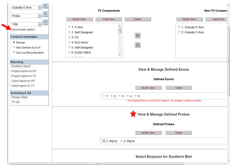
In the Construct section on the left-hand column, click View/Modify Added. It will take you to the View & Defined Probes section. Highlight the probe name that you’d like to modify then click Modify Spec button. It will take you to the Define Probes page. After making changes, click Add/Update to update your new probe.
- How do I delete my probe after I have entered it?
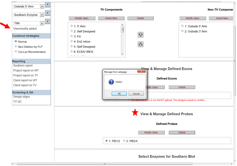
In the Construct section on the left-hand column, click View/Modify Added. It will take you to the View & Manage Defined Probes section. Click the probe name that you’d like to delete then click Delete button. A prompt will ask you to confirm. If you click OK, your probe will be deleted.
- How do I change the way my probe displayed on the schematic diagram?
In the Construct section on the left-hand column, click View/Modify Added. It will take you to the View & Manage Defined Probes section. Click the probe name that you’d like to modify then click Modify Spec button.
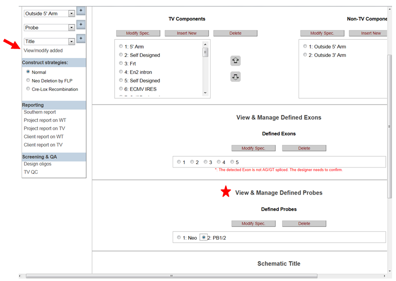
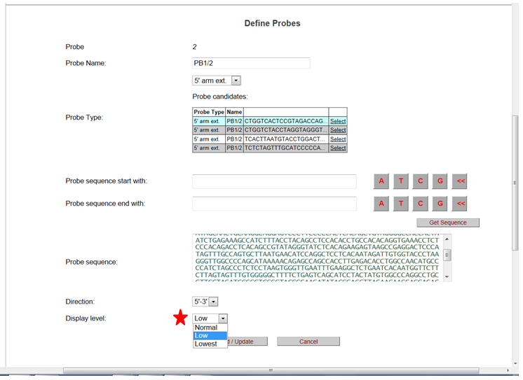
It will take you to the Define Probes page. Click on the drop-down menu for the Display Level and select how your probe will be displayed on the schematic diagram. Then click Add/Update to update your change.
- How do I display a Southern strategy of a specified probe and enzyme on the schematic diagram?
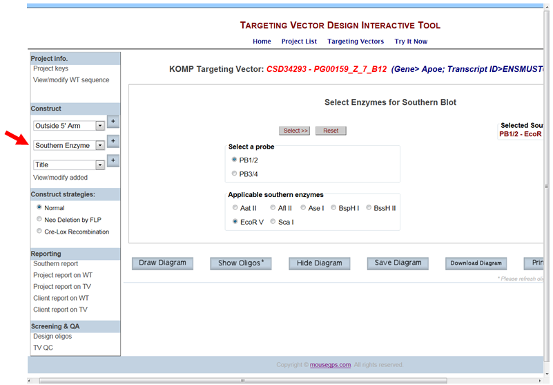
In the Construct section on the left-hand column, select Southern Enzyme from the drop-down menu and click the [+] button. It will take you to the Select Enzymes for Southern Blot page. All probes that you have designed and added are displayed. Select your probe of choice. A list of applicable enzymes for your specified probe is displayed below. Click your enzyme of choice and press the Select button. Your selected enzyme is displayed on the right side.
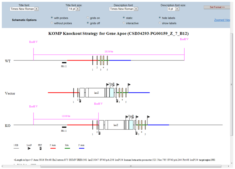
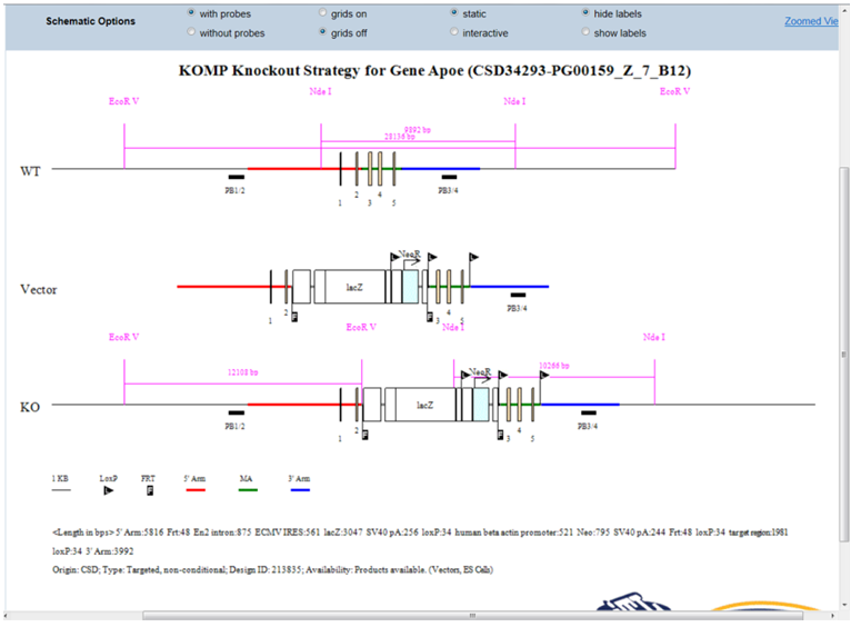
Click Draw or Draw Diagram. A schematic diagram is displayed with the specified probe, the selected enzyme, and the expected sizes for the WT and KO bands.
- How do I display a Southern strategy with two probes and enzymes on the schematic diagram?
In the Construct section on the left-hand column, select Southern Enzyme from the drop-down menu and click the [+] button. It will take you to the Select Enzymes for Southern Blot page. All probes that you have designed and added are displayed. Select your probe of choice. A list of applicable enzymes for your specified probe is displayed below. Click your enzyme of choice and press the Select button. Your selected enzyme is displayed on the right side.
Select another probe and a list of enzymes is displayed below. Click your enzyme of choice and press the Select button. Your selected enzyme is displayed on the right side with the probe name.
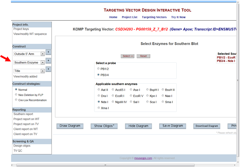
Click Draw or Draw Diagram. A schematic diagram is displayed with the specified probes, the selected enzymes, and the expected sizes for the WT and KO bands.
- How do I remove the selected Southern enzyme from displaying on the schematic diagram?
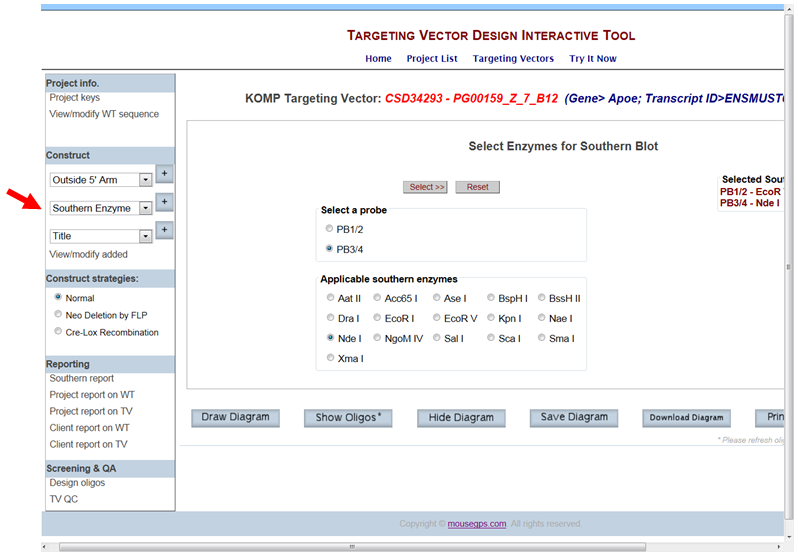
In the Construct section on the left-hand column, select Southern Enzyme from the drop-down menu and click the [+] button. It will take you to the Select Enzymes for Southern Blot page. Click the Reset button. The selected enzyme will be removed from the schematic diagram.
- If I’d like to replace any of the TV components with another sequence (i.e. to replace Neo with Hygromycin or LacZ with GFP), how would I go about doing it?
In the Construct section on the left-hand column, click View/Modify Added. It will take you to the View & Manage Added/Defined Components section. Click the TV Component that you’d like to change, then click Modify Spec button.
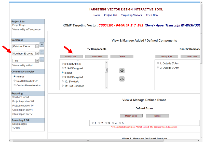
It will take you to the Component Sequence/Specifications page. For the Name, click change.
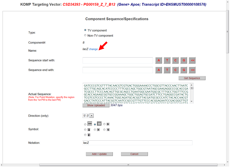
Enter a new name for your component. Type in the start and end sequences then click Get Sequence button or paste the entire component sequence. Change the Notation of the component. Click Add/Update button to save your changes.
* Note when your session ends or if you select another project, your new component cannot be retrieved.
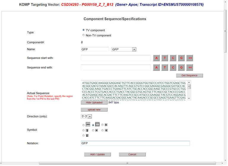
Below is an example of a LacZ cassette changed to a GFP cassette.
- How do I modify the title on the schematic diagram?
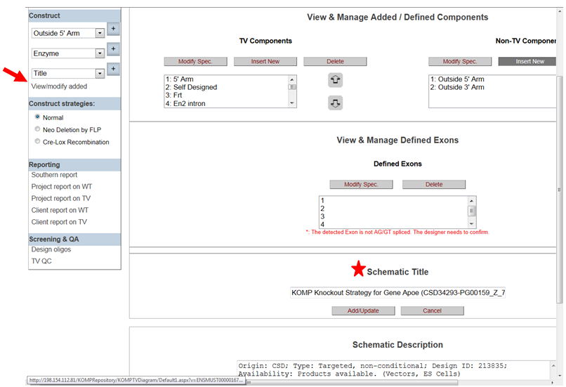
In the Construct section on the left-hand column, click View/Modify Added. It will take you to the View & Manage Added/Define Components page. In the box under Schematic Title, type in a new title and then click Add/Update button.
- How do I modify the description on the schematic diagram?
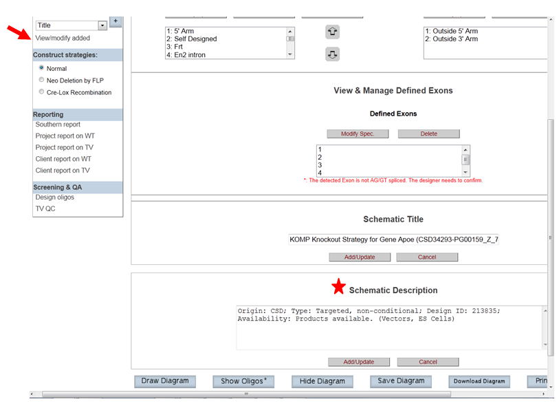
In the Construct section on the left-hand column, click View/Modify Added. It will take you to the View & Manage Added/Define Components page. In the box under Schematic Description, type in a new description and then click Add/Update button.
Construct Strategies
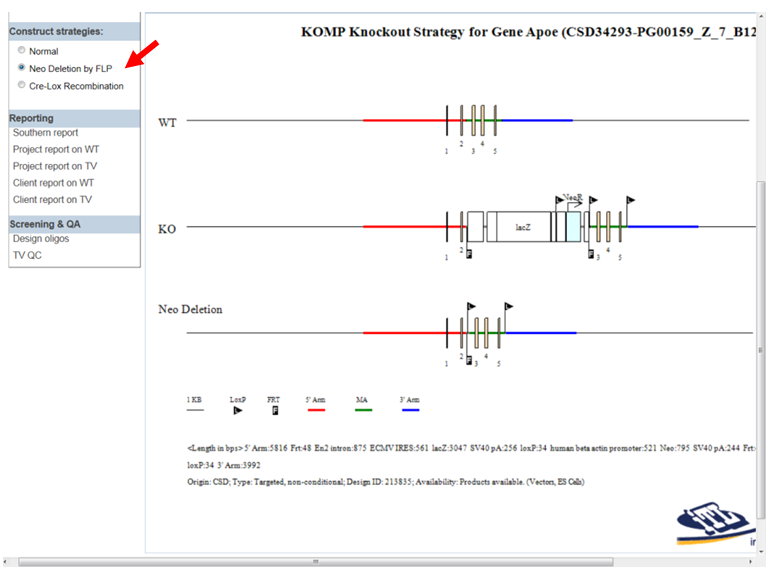
- How do I display the schematic diagram after FLP recombinase has been introduced?
In the Construct Strategies section on the left-hand column, click the bubble next to Neo deletion by FLP. Click Draw or Draw Diagram. The third line on the schematic diagram (Neo Deletion) displays the remaining components after introducing FLP recombinase.
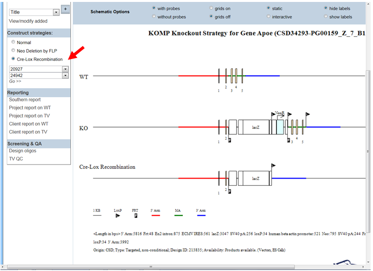
- How do I display the schematic diagram after Cre recombinase has been introduced?
In the Construct Strategies section on the left-hand column, click the bubble next to Cre-Lox Recombination. Select 1st LoxP Site with a drop-down menu of location for all loxP sites is shown. Select the location of the 1st loxP site of your choice. Go to Select 2nd LoxP Site and select the location of the 2nd loxP site of your choice.
Click Go >> button. A schematic diagram is displayed. The third line on the schematic diagram shows the remaining components after introducing Cre recombinase for the selected loxP sites.
Reporting
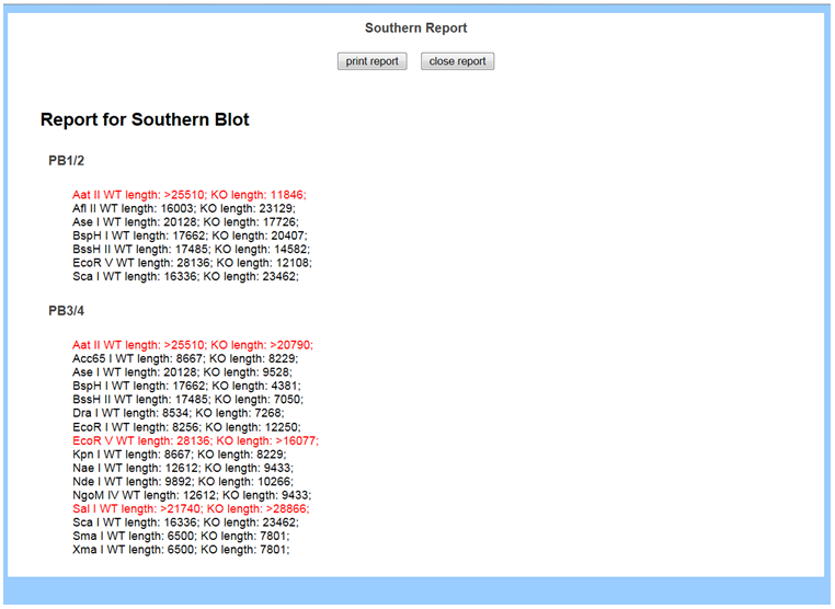
- How do I view possible Southern strategies including enzymes and expected sizes for a specific probe?
In the Reporting section on the left-hand column, select Southern report. A list of all probes that you have designed is displayed in the report including Probe Name, possible enzymes, and expected sizes for the WT and KO. The enzymes that are highlighted in red are not recommended to use.
- How come I didn’t get a Southern report after I entered my probe?
Below are some of the reasons if a Southern report is not generated after you have designed your probe:
- An incorrect probe type was selected for your probe sequence.
- An external probe that was located >10kb outside the region flanking the 5’ or 3’ arm.
- If you selected self-designed as your probe type, then there is no Southern report.
- What is the difference between Project Report and Client Report?
Project Report displays sequences for the forward and reverse strands for your project of interest. Client Report displays only sequences for the forward strand (5’->3’) for your project of interest. Sites of restriction enzymes are indicated only in the Project Report. 5’ and 3’ retrieved homology arms, insertion sites of vector components, locations of oligos, probes, exons, repeats, etc. are annotated in each report.
Note if the sequence is >60kb, the report will not be displayed especially for BAC targeting constructs.
- What is the difference between WT and TV on Project Report and Client Report?
WT displays wild-type genomic sequences before modifications. 5’ and 3’ retrieved homology arms and locations of probes, exons, and repeats are indicated. TV displays sequences after modifications including annotated sequences of 5’ and 3’ retrieved homology arms, vector components, selection cassette, locations of oligos, probes, exons, repeats, etc.
Note if the sequence is >50kb, the report will not be displayed especially for BAC targeting constructs.
Screening and QC
- What is Design Oligos?
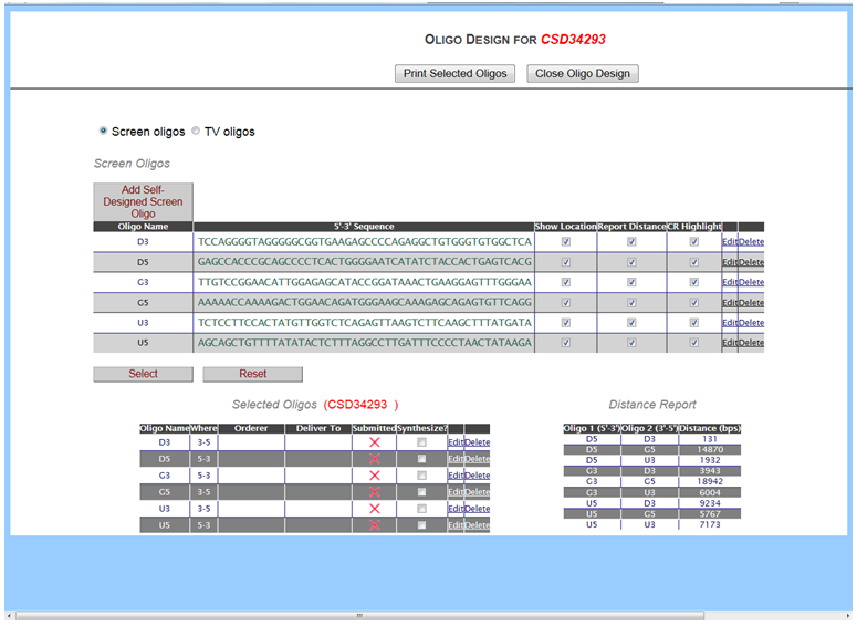
In the Screening & QC section on the left-hand column, click Design Oligos. It will bring you to the Oligo Design page for Screen Oligos. All PCR screening oligos designed and suggested by KOMP or EUCOMM are retrieved specifically for your project of interest. The Oligo Design page displays the Oligo Name, its sequences (5’->3’), location of oligo on the forward/reverse strand, and expected sizes of oligo pairings.
By default, all oligos are displayed on the schematic diagram and the client report.
- How do I display oligos on the schematic diagram and client report?
To view oligos on the schematic diagram, click Show Oligos button in the top panel of the Targeting Vector Design page.
To view oligos on the client report, click Client Report on WT or Client Report on TV in the Reporting section on the left-hand column. Note that oligos that are part of the vector components will not be displayed on the Client Report on WT.
- How do I display some but not all oligos on the schematic diagram or the client report?
In the Screening & QC section on the left-hand column, click Design Oligos. It will bring you to the Oligo Design page for Screen Oligos. All PCR screening oligos designed and suggested by KOMP or EUCOMM specifically for your project of interest are displayed. Find the entry for the oligo that you do not want to display and click Edit. Remove the check from the box for Show Location if you do not want to display the oligo on the schematic diagram. Remove the check from the box for CR Highlight if you do not want to display the oligo on the Client Report. Once done, click Finish for the entry and press Select button at the bottom.
By default, all oligos are displayed on the schematic diagram and the client report. When your session ends or if you select another project, your preferences for displaying specific oligos will be lost.
- How do I find the expected size for PCR amplification for an oligo or primer pair?
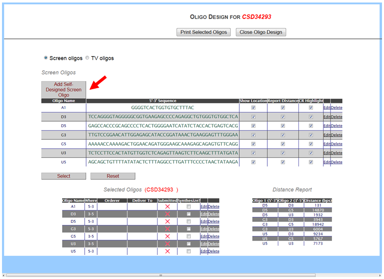
In the Screening & QC section on the left-hand column, click Design Oligos. It will bring you to the Oligo Design page for Screen Oligos. All PCR screening oligos designed and suggested by KOMP or EUCOMM specifically for your project of interest are displayed. In the lower right-hand corner, a Distance Report section displays all possible pairings of oligos for the oligos listed above in the Screen Oligos section. Oligo 1 column is for all forward oligos (5’->3’) and Oligo 2 column is for all reverse oligos (3’->5’). The Distance column displays an expected size in base pairs from Oligo 1 to Oligo 2. This information will provide you the expected size if Oligo 1 and Oligo 2 were used for pairing in PCR amplification.
- How do I design my own PCR oligo or primer and display it on the schematic diagram or the client report?
In the Screening & QC section on the left-hand column, click Design Oligos. An Oligo Design page for Screen Oligos will be displayed. Click Add Self-Designed Screen Oligo. A blank entry will be created on top of the box. Click Edit to enter your Oligo Name and its sequence (5’->3’). Check off the boxes for Show Location, Report Distance, and CR Highlight. When done, click Finish or Cancel if you decide to cancel the entry. Click Delete if you would like to delete the entry. Click Select button below the box to add your new entry. Your new oligo is displayed in the Selected Oligos box. It will show your oligo name and the direction of your oligo (5’->3’ for forward; 3’->5’ for reverse). Note that if your oligo sequence is incorrectly entered, instead of displaying the direction of the oligo, NA will be displayed in the Where column next to your Oligo Name in the Selected Oligos section. For this version, ordering oligos and reporting oligo pairing sizes are not functional. Click Close Oligo Design button on top to close the page.
An example of a newly designed oligo A1 is shown below.
To view your new oligo on the schematic diagram, click Show Oligos button in the top panel. Your new oligo and any other oligos that were checked off in Show Location on the Oligo Design page are displayed on the schematic diagram.
To view your new oligo on the client report, click Client Report on WT or Client Report on TV in the Reporting section on the left-hand column. Your oligo and any other oligos that were checked off CR Highlight on the Oligo Design page are displayed on the Client Report.
* Note when your session ends or if you select another project, your designed oligo(s) cannot be retrieved.
- What is a TV QC page?
The TV QC provides a display of your selected enzyme(s) within the targeting vector and the vector backbone in a circular diagram or a comprehensive list of enzymes with possible cutting sites for the targeting vector and the backbone in a report format.
In the Screening & QC section on the left-hand column, click TV QC. It will take you to the TV QC – Enzyme Cut page. Click Select Vectors button.

Click on the drop-down menu for Const Vector and select Finished Seq. Sequence for the targeting vector is displayed in the box on the top right. Click on the drop-down menu for Vector and highlight Synthetic Backbone and click Select button. Sequence for the backbone vector is displayed in the box on the bottom right. When done, click Select Vectors button in the bottom right.
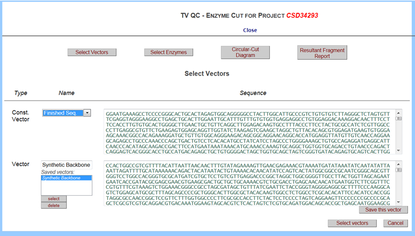
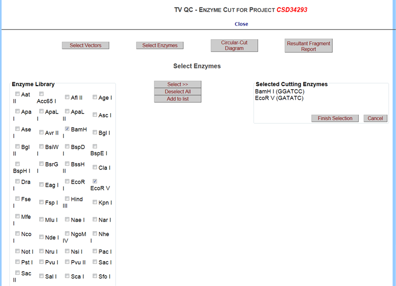
Click on Select Enzymes button and it will take you to the Select Enzymes page. A list of enzymes is displayed on the left. Click on the box next to your enzyme of choice and press Select button. Select your enzyme of choice and click Select button. To select multiple enzymes, hold down the Ctrl key and highlight your enzymes. After selection, click Select button. Your selected enzyme(s) are displayed on the right. To clear all enzymes, click Deselect All. When done, click the Finish Selection button.
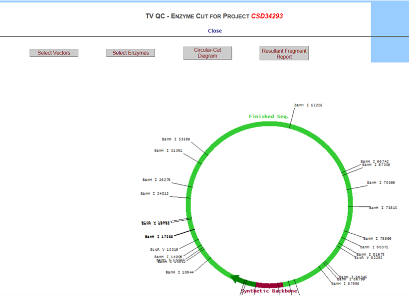
To display the selected enzymes in a circular diagram, click Circular Cut Diagram button.
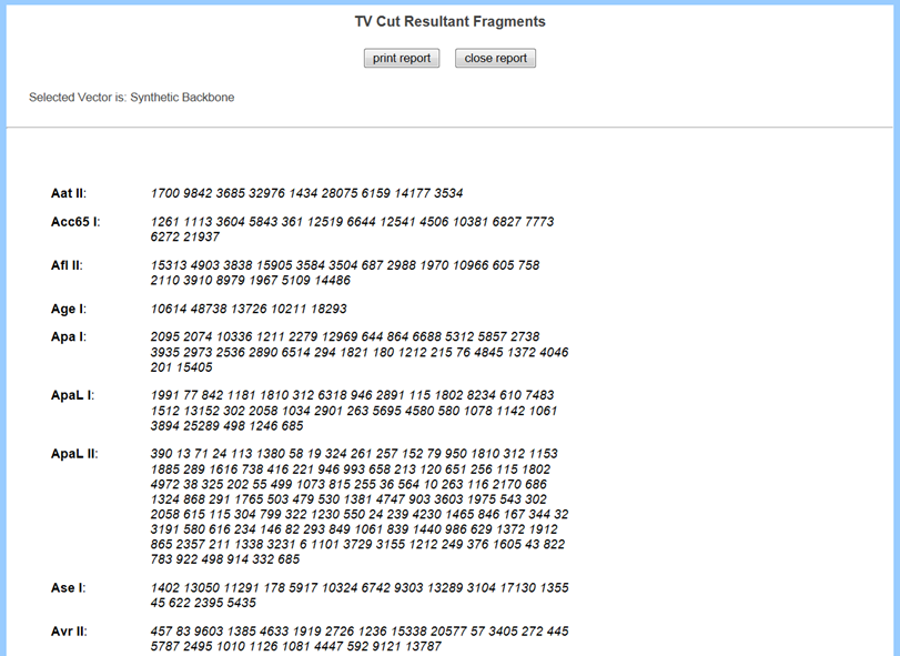
To display all possible enzymes with its cutting sites in a report format, click Resultant Report Fragment button.
Key Functions on Top Panel
- How do I get to the Ensembl website from the Targeting Vector Design page?
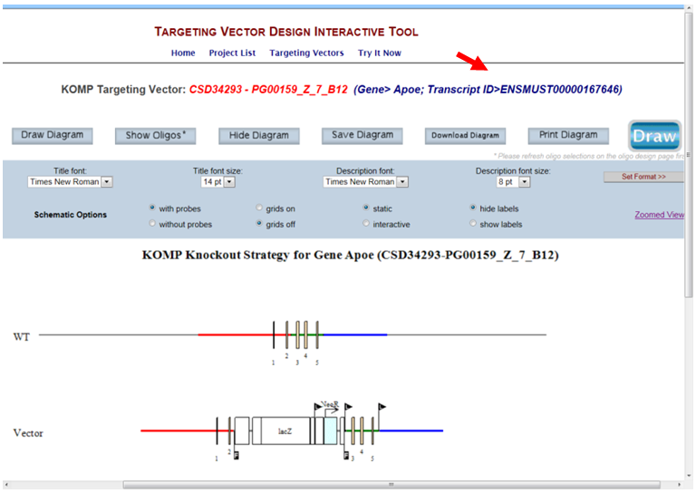
Click on the Gene name or Transcript ID, it will link you to the Ensembl for your gene of interest.
- How do I display my selected targeting vector on the schematic diagram?
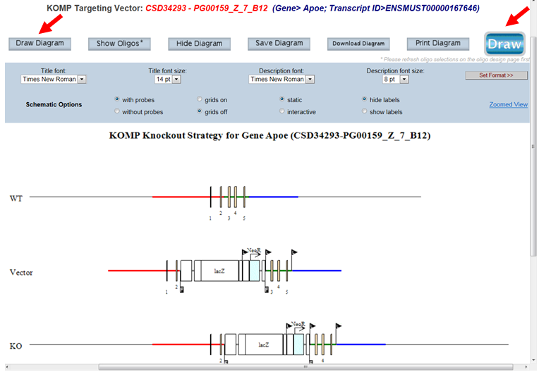
On the top panel, click Draw or Draw Diagram button and a schematic diagram for your selected targeting vector will be displayed.
- What is displayed on the schematic diagram?
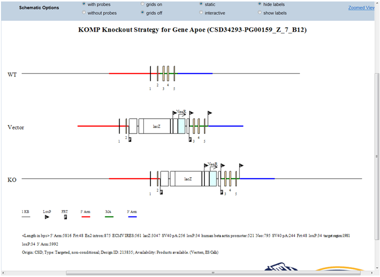
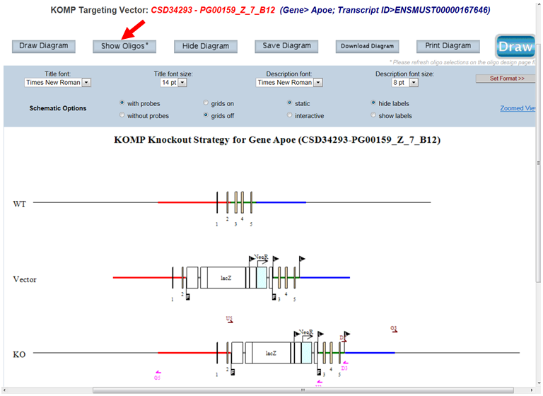
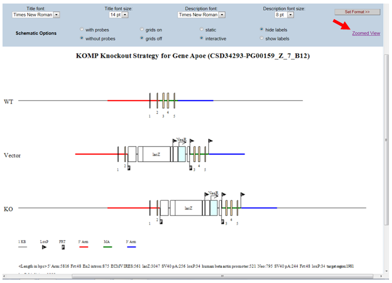
The title of the schematic diagram is displayed on the top with the gene name (i.e. Apoe), the project ID# (i.e. CSD34293), and the targeting vector name (i.e. PG00159_Z_7_B12).
Three images are shown on the diagram. The first image (WT) displays the wild-type genomic sequences with boxes as exons and color-coded lines for 5’, 3’, and middle arms. The second image (Vector) displays the vector components without the vector backbone. Flags are used to indicate FRT or loxP sites and boxes are used for cassettes. The third image (KO) shows the targeting vector integrated into the genome. The WT sequence is replaced by the targeting vector.
Legends of symbols and colors used in the diagram, lengths of the retrieval arms and vector components, and pertinent information about your selected project are provided below the diagram.
- How do I hide the schematic diagram?
On the top panel, click Hide Diagram button and the schematic diagram will not be displayed.
- How do I display my selected oligos on the schematic diagram?
On the top panel, click Show Oligos button and all oligos are displayed forward or reverse direction on the KO strand in the schematic diagram. Note: If you make any changes on the Oligo Design page, you must click Select first on the Oligo Design page. Then click Show Oligos to display changes.
Schematic Options
- How do I change the font style and size for the title on the schematic diagram?
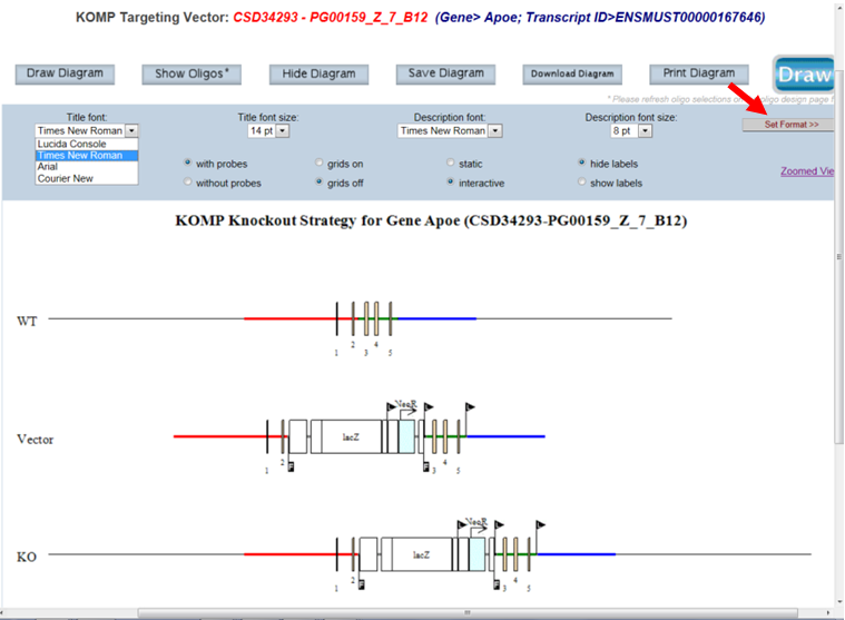
Click on the drop-down menu for Title font or Title size. Select the font style or size of your choice and press the Set Format button to display your change. Default is Times New Roman at size 14 pt.
- How do I change the font style and size for the description on the schematic diagram?
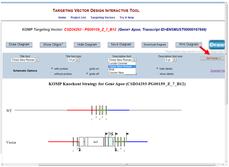
Click on the drop-down menu for Title font or Title size. Select the font style or size of your choice and press the Set Format button to display your change. Default is Times New Roman at size 8 pt.
- How do I display/hide my designed probe(s) on the schematic diagram?
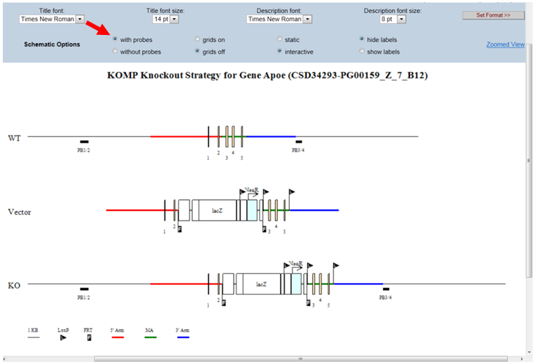
In the Schematic Option on the top panel, click the bubble next to With Probes to display your probe(s) or click the bubble next to Without Probes to hide your probe(s).
- How do I display the relative distance or size on the schematic diagram?
By default, the grid is off. In the Schematic Option on the top panel, click the bubble next to Grids on. A grid of vertical lines will be overlaid on top of the schematic diagram. The space between two vertical lines is 1kb long. This will allow you to estimate the distance or size on the schematic diagram.
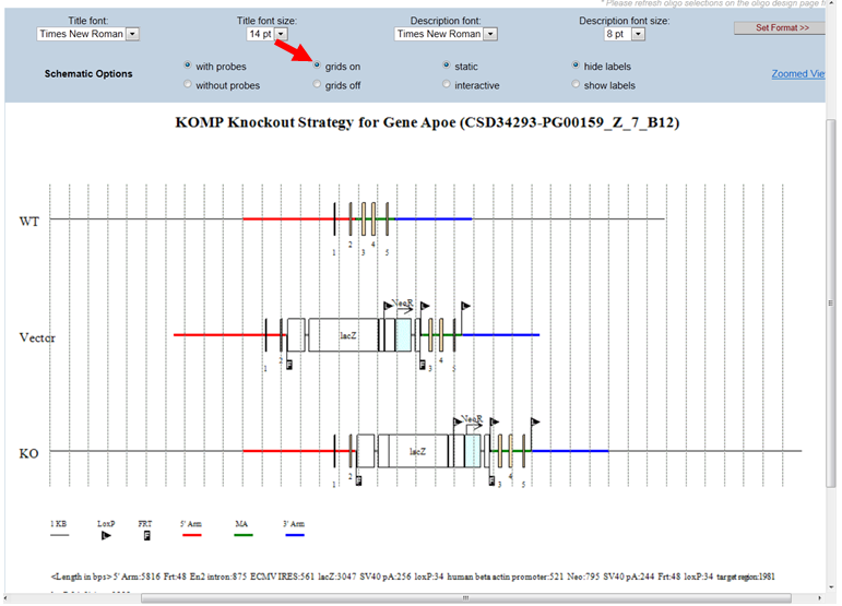
- What is the static or interactive button on the schematic diagram?
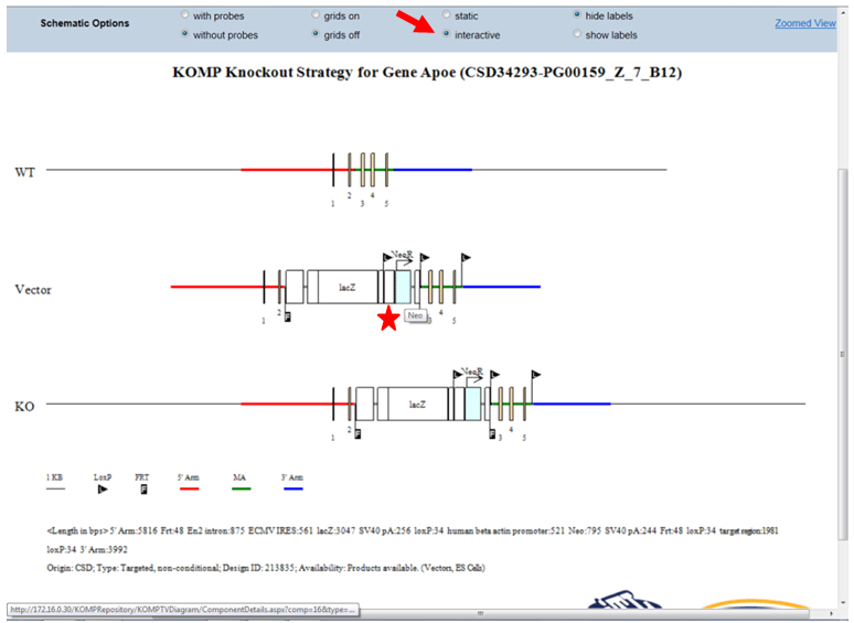
By default, the schematic diagram is in a static mode. In the Schematic Option on the top panel, click the bubble next to Interactive. This will allow you to view the schematic diagram in the interactive mode. When moving your computer mouse on top of the image, a pop-up box will indicate the description of the component. The example below shows a pop-up box indicating the Neo cassette (in red asterisk).
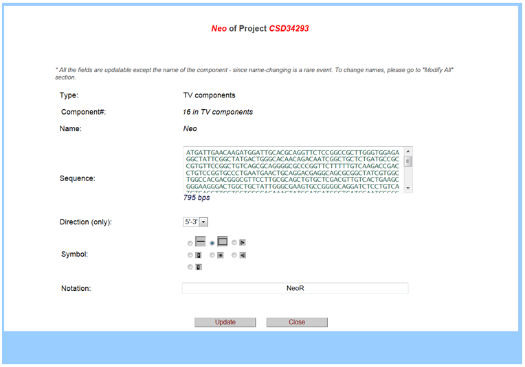
When clicking on the pop-up box, another window will be opened with details about the vector or non-vector component. For example, below provides the sequence and size of the Neo cassette and other details.
- How do I show/hide all the labels on the schematic diagram?
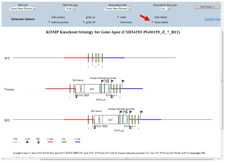
By default, the schematic diagram hides all labels of the vector components. In the Schematic Option on the top panel, click the bubble next to Show labels. Details of the vector components will be displayed on the Vector and KO images.
- Can I save the schematic diagram?
For this version, your schematic diagram cannot be saved.
- Can I download the schematic diagram?
For this version, your schematic diagram cannot be downloaded.
- How do I zoom in to see details of the schematic diagram?
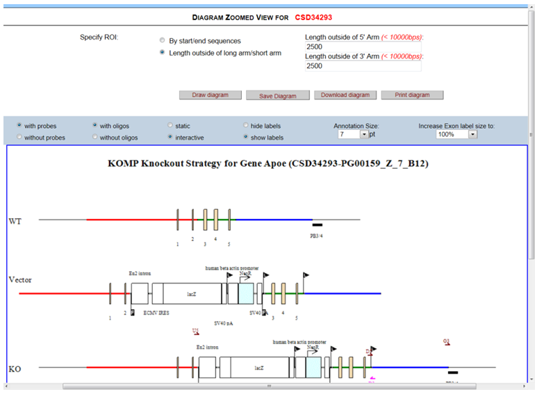
In the Schematic Option on the top panel, click Zoomed View.
Another window will be opened for the Diagram Zoomed View page. There are 2 ways to specify your region of interest (ROI). The first method is by entering the start and end sequences of your ROI outside the 5’ and 3’ arm. A minimum of 40bps is required per arm. The second method is by entering the length (in basepairs) flanking outside the 5’ and 3’ arm for your ROI. The maximum is 10,000bps. Then click Draw Diagram button. An enlarged and zoomed-in schematic diagram is displayed below. The Save Diagram and Download Diagram are not functional for this version. Select any changes in the Schematic Options and then click Draw Diagram to display changes in the schematic diagram. Below is an example of an ROI that is specified by length outside of 5’ or 3’ arm. The length was entered for 2500 bps.
